State diagram
Created 2006-12-11T06:09:44.297Z, last edited 2006-12-11T09:45:52.629Z
State diagram
A link to the full resolution version of the image is at the bottom.
I have to admit that for many, many years I found state diagrams confusing. I could never work out which bit was which. At first glance they look very similar to flowcharts, but the similarity is superficial even though they can both be used to represent the same logic.
The way I think about state diagrams these days is as stones in a pond. Each stone represents a state and a state is where the object instance is at rest waiting for the next input. At each transition occurs when a message is received and the contents of the message determine which way the object jumps. In this analogy then we can see that messages that aren't understood by the object would cause it not to know which way to jump and so it'll probably fall off and get wet.
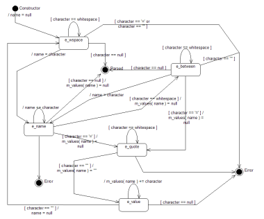
The state diagram here is in UML. The states that occur during the processing are represented by chamfered rectangles. In UML a state diagram may only have a single start state (represented by a filled in spot). There are two end states (with one on the diagram twice) which are shown by spots with a circle around them.
The reason why the Error state is shown twice is simply to avoid having to have lines cross in the diagram. The implementation doesn't use Error as a state as it throws an exception1 instead. In this diagram I take the view that the Error state is needed in order to represent what is invalid in terms of the input. If there is any input that may appear for which there isn't a state transition then this represents an error in the design. By making the error condition explicit in the design we can then properly tell the difference between an expected error (invalid input) and an unexpected error (something missing from the design).
The other states are:
e_wspace—Means we are processing the white space that occurs between attributes.e_name—We have seen the first character of an attribute name and are expecting more, or a delimeter.e_between—We have seen a space whilst processing an attribute name so we are either in the whitespace between the attribute name and the equals sign, or we are in the whitespace between an attribute with a null value and another attribute. We do not yet if the attribute is now complete or if there is a value for it.e_quote—We have seen an equals sign which means that the attribute must now have a value and the value must be surrounded by double quotes.e_value—We are processing the value. There must be a closing double quote.
The lines represent both the conditions and the actions. In UML the condition is within square brackets (i.e. [character == null] from e_value to Error) and the actions are introduced by a slash (i.e. /name = character in the transition from e_wspace to e_name). A line with no conditions simply means any other character. There can of course only be one of these from a given state. Many of the state transitions have no action associated with them.
m_values should be taken as some sort of associative array that holds the attribute values. In the diagram I use curved brackets to show the dereferencing rather than square brackets purely because square brackets are part of the UML notation and my UML tool sometimes gets confused.
The dirty secret with state diagrams is of course that they're not really any easier to write or debug than the code used to express them. This one certainly wasn't correct before the code was being written and tested (and knowing me the diagram probably isn't a 100% accurate representation of the actual code).
They do have value though in documenting what the code is doing. Although they are no easier to write than the executable code, they are certainly easier to read.
Other sizes


© 2002-2026 Kirit & Tai Sælensminde. All forum posts are copyright their respective authors.
Licensed under a Creative Commons License. Non-commercial use is fine so long as you provide attribution.